This post will look at the hardware inside the GameTrak and describe how to mod it to make it work with a PC if you happen to have the most common Playstation 2 version.
The GameTrak by In2Games is a cheap and quite popular controller for experiments with motion control, homebrew virtual reality and all kinds of other hacks. The original hardware is meant to be used with Playstation 2 and has to be modified before it will work with PC, however, it is possible to find the PC version too. The device is out of production but can be found cheaply (~25€) on eBay. It was reviewed by Sebastien, including an example of how to use it with a PC.
Opening the Gametrak requires removal of the 6 screws on the underside, hidden under the rubber feet. You have to either remove the feet or puncture them with a screwdriver:
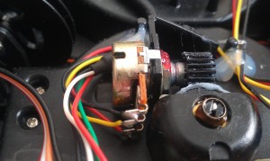
Once the cover is off, it is quite obvious how the device works. There are two analog joysticks, each sensing the x-y movements and the third axis is sensed using a spool of wire connected to a potentiometer using a pair of gears. The pots are all the same value around 5k, linear.
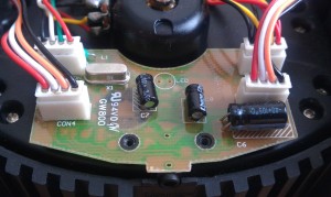
The PCB is held down by 4 screws, removing those reveals a black epoxy blob covering the controller chip. Unfortunately, that pretty much makes the device un-repairable but it is common in low cost consumer hardware. The board is single-sided, with only few parts. It is obvious that the GameTrak has (or was meant to have) some undocumented functionality – there is an unpopulated footprint labeled LED and the jack plug used to connect the foot switch is labeled “Expansion port”. Also all three traces from the stereo plug are connected, clearly intended to be used as some sort of serial interface.
Flipping the board up reveals the epoxy blob and a very important detail – the revision number. The Rev 2 GameTraks can be easily modified to work with a PC with a little soldering, as described by Alex. Unfortunately, the older rev 1 boards, as the one in the photos here do not work with the mod. The chip obviously lacks the required code in the firmware. The board is also quite messy, with some bodge wires, extra resistors and caps soldered directly to the pins, hot melt gunk all over the place, etc. Someone was obviously in a hurry to get the gadget on the market. The rev 2 board incorporates all those modifications already and includes the PC/XBox support.
If you are unlucky and are stuck with the rev 1 GameTrak, the simplest solution how to make it work is to replace the electronics. Basically, we need to measure 6 analog values from the potentiometers and one button and send that information over USB to the PC. This can be done in many ways, but I have tried to follow these criteria:
- Same protocol – the modified device should enumerate as a HID joystick, with the same mapping/functionality as the original GameTrak on the PC. This will allow to use software like VRPN without modifications with both types of GameTrak.
- USB HID support (obvious)
- Cost. GameTrak is around 25€ on eBay, a 30-40€ mod may not be very popular. On the other hand, it is not easy to get the costs down under cca 15€ with a one-off production.
The criteria rule out some popular solutions like Arduino (20€+ for the board, won’t fit inside the GameTrak and has only serial, not HID support), Teensy could work (can be reprogrammed for HID and is cheaper), but its form factor would make mounting and connecting it inside complicated. Thus custom board is called for.
I am more familiar with Atmel ATMega/ATTiny chips, unfortunately USB with these is not simple. I have tried the bit-banged software VUSB solution, but that is not robust, it doesn’t work right on many USB ports and is fairly sensitive to component choice. Not good if the design is to be reproducible. Furthermore, only low-speed USB is possible, limiting the maximum size of the packet that can be transferred at once to 8 bytes, which isn’t enough for 6 16bit values from the GameTrak.
ATMega series chips with hardware USB are only few. ATMega32u2 costs around 4€ in single quantities by RadioSpares. However, closer look into the datasheet reveals a showstopper – those chips have no A/D converters! The larger ATMega32u4 variant with the required A/Ds is around 6.5€ in single quantities. Not great, half of the budget for the board would be eaten up by the MCU alone.
I looked at the Microchip PIC series and they do have a lot to pick from. I have originally gone for PIC18F25J50 (same as the more popular 2550, but only 3.3V and costs about half). This PIC is cheap (~2.7€), works a treat and has good compiler and debugging support with the cheap PICKit programmers. However, then I have discovered that there are essentially no PICs that have both EEPROM and USB interface at the same time – I wanted to use EEPROM for storing calibration data as every GameTrak is slightly different. I guess that is why there were the bodge resistors on the original board. OK, external I2C EEPROM can be added, they are cheap. I had the setup working on the breadboard, but it was quite a bit of stuff to mount on the PCB – 5 to 3.3V voltage regulator, external EEPROM, PIC, the connectors … It would have been a tough squeeze to fit on a single sided board. I didn’t want to bother with double sided because I can do boards only using toner transfer right now and double sided using toner transfer is a major pain.
Then I discovered the PIC18F14k50 MCU – cheap (only 2€ a piece!), has 256B of EEPROM, USB controller and built-in voltage regulator, allowing the chip to run directly from 5V USB voltage while providing the correct signalling at the 3.3V level! Furthermore, the built-in regulator is of an LDO type and is suitable even for the stringent requirements of USB bus-powered devices (current draw in suspend). That means that I can save two extra chips, use a smaller MCU chip (20 pins vs. 28 pins) and simplify my circuit. A win-win situation. The only downside is that the 18F14k50 PICs have no debugging support whatsoever. I would have to either buy the expensive “debug header” (a special version of the PIC with the extra debugging circuitry and pins) or debug the program on the 18F25J50 and then recompile for the smaller PIC. Surprisingly, that worked a treat, apart from few minor adaptations like register names, configuration word and a linker tweaks needed to get the USB buffer into the dedicated USB memory on the 14k50, there were no issues. A pleasant surprise, especially considering that PIC18 was a completely new architecture for me.
I have built a prototype on the breadboard (schematics as PDF), in order to make sure that I can actually fit everything into the tiny memory of the PIC – it has 16kB of program FLASH, but only 768B of RAM and out of that 256B is dedicated for the USB controller. So only 512B are useable for regular code. The prototype used 3 USB connections at a time – the upper left mini-USB breakout is the main one, for the USB HID connection. The USB-B plug in the middle is an FTDI serial adaptor for debugging and the third connection was through the PICKit. The two trimpots were used to simulate the pots on the GameTrak, along with the button. The LEDs were only for debugging.

Schematics (full sized PDF)
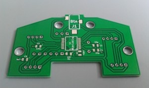
For the PCB I have decided to bite the bullet and have the board manufactured by Itead Studio. I have used KiCad and designed a single sided board. I have tried to build it using the toner transfer process, but I couldn’t get the traces filled sufficiently to avoid cracks, especially in the thin traces. Itead can do the board without problem, double or even four layers for about 2€ a piece + shipping, including solder mask and silkscreen. Basically, at that price it isn’t worth the trouble doing it at home. In about two weeks after the order I had the manufactured boards in my hands, not bad for shipping from China!
Populating the board was a breeze, except that I didn’t have the required 220nF-470nF cap for the voltage regulator, so I had to resort to stacking two 100nF ones. Also the electrolytic cap in the corner should be 0805 and not 1206 size, but I haven’t had one in my part box. So I have soldered the 1206 one on the track in order to be able to complete the device. Not pretty, but works OK.

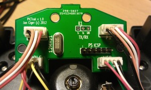
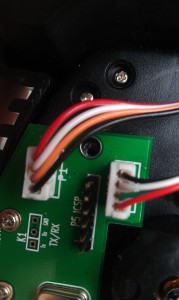
Populated and connected board – the plastic on the connector for the foot switch is a bit melted because I have desoldered it using hot air from the original board (RS doesn’t seem to carry this connector type). Also there are two small bodges on the left side – I didn’t have the right sized caps and had to improvise a bit.
Unfortunately, as usual, Murphy stroke and one of the mounting holes is off by about 2 millimeters. Nothing major, certainly not worth re-spinning the board, but one of the mounting holes cannot be used. The worst part? I had the hole in the right place before but after a test with a printed out mockup of the board it seemed to be off so I have moved it. Oops…
A quick test of the device – and yes, it does work! I have tested it with both VRPN and jstest (Linux joystick testing utility) and everything seems to work properly. It works with Windows as well.
[24114.898661] usb 1-1.5: new full-speed USB device number 5 using ehci_hcd

[24115.011447] usb 1-1.5: New USB device found, idVendor=14b7, idProduct=0982

[24115.011449] usb 1-1.5: New USB device strings: Mfr=1, Product=2, SerialNumber=0

[24115.011451] usb 1-1.5: Product: GameTrak PIC

[24115.011452] usb 1-1.5: Manufacturer: VRGeeks - Jan Ciger 2012

[24115.012857] input: VRGeeks - Jan Ciger 2012 GameTrak PIC as /devices/pci0000:00/0000:00:1a.0/usb1/1-1/1-1.5/1-1.5:1.0/input/input20

[24115.012998] generic-usb 0003:14B7:0982.000A: input,hidraw7: USB HID v1.11 Joystick [VRGeeks - Jan Ciger 2012 GameTrak PIC] on usb-0000:00:1a.0-1.5/input0

(janoc@dvalin)-(01:34 AM Mon Jul 30)-(~)

$
Here are the design files:
- KiCad project
- HEX file for the PIC18F14k50
- C code (GPL licensed) Unfortunately, the USB stack from Microchip is not freely redistributable, you have to download it yourselves.
NOTE: If you use the HEX file above, you will need to calibrate the device before use, otherwise the joystick axes will be unresponsive. Hold the foot switch down and plug the GameTrak in. The device will not be recognized by the PC, but that is normal – it is in calibration mode. Move both joysticks through all extremes and extend both wires to the maximum too. Once done, press the foot switch again to terminate the calibration. The values will be stored in the EEPROM, so there is no need to do this procedure again unless you accidentally enter the calibration mode on powerup.
I have also some boards left, if someone is interested contact me.
All boards I had are gone, sorry! I am not planning to order more unless you want several – it is not economical for me to keep stock and minimal order from ITead is 10 boards. You can have them made yourselves – the Gerbers are in the KiCad project in a subfolder.
Update 13.04.2013:
Géry Casiez from the University of Lille, France has sent me this wonderful demo that is using two “PICTraks” built using the project above. He has also built a library for interfacing to the Gametrak/PICTrak if you do not want to roll your own or do not want to use VRPN for some reason: libgametrak





Hi Jan, great work here. I just found out that I have a REV1 gametrak. Have you hit the 10 requests already? Just asking, I could order one, please let me know.
Thanks,
Francisco
Hello Francisco,
No, sorry, no boards are left – it is clearly indicated on the page.
I am not planning on ordering another batch – it wouldn’t be economical for me. However, if you need one, download the Kicad project – the gerber files are included in the zip file and then you can order your own PCB from e.g. Seeed, iTead, OSHPark or any other PCB fabricator simply by uploading them (just keep in mind that one of the mounting holes is unusable, as described above).
Best regards,
Jan